Fox Tango International FT-102 Relay Page
By C.L. Maher W4CLM
RF Unit PB-2342B
12 VDC Relays RL01, RL03, RL04, RL05
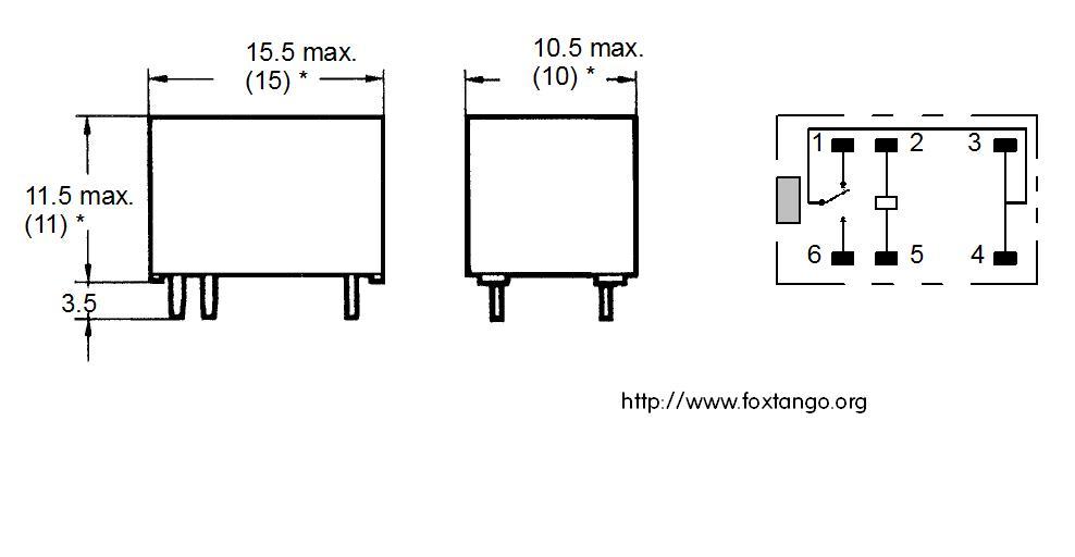
Fig "A"
OEG OUA-SS-112D OEG OUA-SS-124D FBR211A D012-M Omron G2E-184P-M Omron G2E-134P-M Omron G2E-187M
Board Qty RF Unit PB-2342 4 IF Unit PB-2343 1 Local Unit PB2345 1 Final Board PB-2355 1

RL02 installed on the RF Unit PB2342
Fujitsu type FBR221A
12VDC Relay RL02 Original FBR221A-D012
Board Qty RL02 RF Unit 1
Final Board PB-2355 RL01 on the PA board

Relay Unit PB-2345, RL01 antenna T/R relay
12 VDC Relay Antenna T/R Relay

Fig "B"
Original RL01 on Relay Unit Omron G2U-112P/10V
G5LE-14 Automotive relay available in USA
OMRON G8SN-IC7-CUK Automotive relay (Europe only) not available in USA
Board Qty Relay unit PB-2345 1
FT-102 Main Chassis RL1 & RL2
Guardian Type 1315-H
4PDT 5 AMP Contacts

NTE R12-17D3-12
Everything you ever want to know about FT-102 Relays.
The Truth About FT-102 Relays !
When it comes to the FT-102 transceiver the first topic that pops into one's head is RELAYS!
The fist thing you always hear about regarding the FT-102 is just how bad the relay situation is! I really beg to differ on this because it usually winds up being only one or two relays out of the whole set that give you a problem, thus the general opinion is that all the relays are faulty. That will not be the case, but either way you look at it these rigs are now going on some 24+ years old so you really can't go wrong replacing them all. If you need a set, See the Fox Tango Club Candy Store for our FT-102 Relay Replacement Pack. Also see Installing New Relays In Your FT-102.
RF Unit PB-2342B
12 VDC Relays
RL01, RL03, RL04, RL05

In an effort to clear up any misunderstanding about the FT-102 and the relays we will take a look at each individual relay its replacement and or modifications for replacements. The relay that is most commonly seen relay in the FT-102 RF Unit PB-2342 is (RL01, RL03, RL04, RL05) if your transceiver has the original small blue cube relays as shown in the photo above these were made OEG Relays (TYCO Electronics) the more commonly used replacement part for these relays is the OMRON G2E-184P. The relay is a miniature, low cost single-pole 12 VDC relay . Pretty straight forward in that it is wired for normally open (N/O or normally closed (N/C) contact. You should make note of the following, so FT-102 were modified so that RL04 and RL05 are wired for 24vdc, see notes below for more on this.
 Omron G2E-184P-M See:
Omron G2E data
sheet here. If Yaesu USA has any left the part number as of 1/12/06
was M1190032 at a cost of $4.50 each when they were available from
Yaesu parts, but they no longer carry these in current stock.
Omron G2E-184P-M See:
Omron G2E data
sheet here. If Yaesu USA has any left the part number as of 1/12/06
was M1190032 at a cost of $4.50 each when they were available from
Yaesu parts, but they no longer carry these in current stock.
See figure "A" to the left side. As noted you will find four of these on the RF Unit PB-2342, one on the IF Unit, one on the local unit and lastly one on the final board (*needs to be removed) just under the 6146 tube sockets. All can be replaced with the OMRON relay G2E-184P-M fully sealed 12vdc relay which can easily be found in the United States. There has been some discussion as to a modification where RL-04 and RL-05 on the RF Unit are wired together in series for 24Vdc operation. There is some controversy about this as to whether or not one should use the 24 Vs 12 volt relays. My gut feeling on this is to leave the relays as original set up for 12Vdc. After discussing this subject with Malcolm (NC4L) the FT-102 Guru here in the USA, he believes the 24vdc modification to the RF Unit was used for a ballast for the front end supply. In other words instead of using the 12 volt supply for the relays - they found that the DC for the front end was better slightly loaded down. The circuit for the 24 volts is not the most sophisticated or precision item as it is only zener regulated. As per Malcolm "they looked around and figured - lets power two relays with the front end supply so that the energy for the loading effect at least has a useful purpose. I am pretty sure that was the case as they certainly have an ample amount of 12 volt power to run the relays." My gut feeling on this subject is to leave the rig alone, if it's wired for individual 12Vdc relays and the transceiver remains operation, then don't fix what is not broken.

Other Cross References for the G2E
FUJITSU: FBR211SC/SE
OEG: OUA/OUAZ OUA-SS-124D
SIEMENS: A/B201/V23101
GEI LS1-012-6L1S
RF Unit RL02 Relay

RL02 RF Unit PB2342. This single relay in the FT-102 that stirs up the most controversy among those in the FT-102 community of users is that of RL02 on the RF unit as it is no longer available. Originally made by Fujitsu of Japan relay type FBR221A DO12 is shown below. Two schools of though currently exist for repair or replacement of this relay. Currently however the club has a complete relay kit available for the FT-102 (Less RL1 & RL2) See: Fox Tango Candy Store for the FT-102 relay replacement kit. Check for availability as we only have a limited supply of original Fujitsu relays in a complete relay kit if you are in need of this part.


Yaesu part number for this item was P/N 70000031 (BR221D012) 12v they also made a 9 volt version of this relay P/N 70000034 (BR211AD009-M) 9v which could be modified for use in place of RL02 with a 3v voltage drop on the coil if it becomes necessary to resort to this.
First school of thought on this comes from Jose - (EB5AGV/EC5AAU) in Spain. Jose has come up with a most ingenious way of changing this relay over to a more commonly available Omron relay G6A-234P, see Jose's tutorial for relay replacement EB5AGV's FT-102 relay substitution TUTORIAL you have got to give Jose credit for investigating a suitable replacement and in his ability to come up with a creative process for replacement of this hard to find relay.
The second school of thought on this matter comes from (NC4L) Malcolm (Mal) the undisputed guru of the FT-102 here in the United States. Mal has come up with an very intricate restoration process where by he finalizes the restoration by gold plating the relay contacts. See: www.members.aol.com/NC4LMal This procedure while time consuming manages to leave PB-2342 in it's original condition without modification. The following I received from Mal in an Email 1/21/06
The procedure starts with the removal of the top of the relay and
placing the relay in an ultrasonic cleaner to remove any particulate
matter. The relay is then dried. After this the arms holding the
contacts are bent back with special tools to expose the surfaces of the
contacts. The small needle nose pliers that I use for this had to be
fashioned with a Dremel tool and high speed diamond wheel which I used
to get a rounded surface for the side of the pliers jaw. Without this
remodeling, the flat surface of the jaw and the sharp angle at the side
of the jaw leaves a crimp in the copper arm holding the contact. This
crimp damages the arm and eventually causes the arm to fall off with the
repeated flexion that comes with the operation of the relay.
With all the contacts openly exposed they are physically cleaned
with a soft brass brush and the high speed Dremel tool until all the
foreign matter is removed and the contacts are made bright and shiny.
Now comes the hard part. The copper arms holding the contacts
which have been splayed back have to be gently returned to their
original position and tensioned for proper force. I do this by hand and
it is a very time consuming and exacting endeavor.
When this is completed the unit goes for its first gold plating.
For half of the gold plating session the arms are held in the open
position to get those contacts plated. Then the special plastic shim
holding the contact open is removed and the unit is plated again to get
the other two contacts.
The unit is again rinsed and dried before the conditioning
process is started. This is done by repeatedly cycling the contacts with
a high current flowing to all the contacts. I found that this is
necessary to reform the contacts since no matter how carefully I
reposition and tension the arms the fit may not be perfect. This high
current during the make and break cycle heats the metal of the contact
and deforms it so that it fits precisely to the matching opposite half.
Too few cycles will not give a good fit and too many will permanently
damage the contacts. This information is proprietary so we will go on to
the next step.
The unit is now replated for all four contacts in the gold
solution bath so that the previously heated portions of the contacts
from the conditioning process also gets a proper plating. The unit is
again dried and the top replaced.
But you cry are we finished. The answer is not yet.
The last step is quality control where the unit is placed on a
milliohm meter and cycled 50 times per contact. No one reading on any
contact can exceed 50 milliohms (.05 ohm) or the unit is not acceptable.
For this auction and in my own repair work a special gold plated
socket will be supplied to be installed so that if a problem occurred,
the relay can be removed and replaced without dismantling the radio to
unsolder it. However if you are brave just solder it in place as I am
confident it will be and stay good.
Relay 02 is in close proximity to a transmit mixer that runs
continuously in receive as well as transmit. That circuit is in the
middle of the RF board (inside the metal baffle) on the upper side.
Because of this other circuit the relay was meant to be flat to the
surface the board to reduce cross modulation. I file the shoulders of
the socket to get another millimeter closer to the plane of the board to
reduce this interaction to a minimum. As mentioned above the special
socket (which is also gold plated) is supplied with the auction.
Well, that about completes the description for this auction.
Enjoy the photo below which will permit you to conceptualize the this
process better.
Some other points - a fellow ham in Spain has a modification
where a different configuration pin out relay is used. The modification
entails soldering to the bottom of a socket which is then used in the
holes for the original relay. However the traces on the bottom of the
board also have to be cut and several patch wires are soldered in place.
Unfortunately these wire paths now cross over one another when they
should not. This reduces the performance of the front end because of
cross modulation and signal leakage. I have photos of a board where this
abomination was performed and a comparison board to show what the final
product of that effort looks like in relation to the original design. If
you are interested in those photos check my website at
www.members.aol.com/NC4LMal
. By the way if you have ever tried to solder a small wire to the
underside of a small plastic socket with lead spacing of 0.1 inches,
expect a lot of melted plastic and its fumes. You will need a very fine
soldering pencil tip and very small gauge solder along with the vision
of a preteen
Final Board PB-2355 RL01 on the PA board
Another relay of interest in the FT-102 is RL01 on the final board PB-2355. See Photo to the left of the PA board, RL01 should drop the PA screen voltage from 210v to 180v when the transceiver is switched to the 10 meter band. The circuit on the final unit can bee see on page 63 of the FT-102 technical supplement in the lower right hand corner see L07, R06, Q01 transistor switch (2Sc1815) which then goes to the coil of RL01, ironically none of the parts listed here will show up on your schematic diagram. How is RL01 switched on and off? In the lower right hand corner of your final unit you will see a contact at L07 Labeled 28 MHz. There is a brown wire on this corner of the board. That brown wire, if you're willing to take the time and trace the brown wire all the way back to the Local Unit PB-2345 its point of origin is tack soldered on to the Local unit at the Cathode end of D36 (It could be on D35/36/37/or/38) as all the cathodes of these diodes are tied together on the local unit. The other end of these diodes goes to P40/J01, which then goes to the band switch 10-meter positions
 RL01 of the PA board should be bypassed, (Remove it!)
Yaesu initially placed it there to switch the screen voltage to a lower
value when on ten meters for better efficiency. The relay was inconstant
and gave them troubles so they just left it in the radio without
switching it on or off. Since they didn't make the radio with RL01
active for regular production they took it out of the schematic so you
will not see it although it is most certainly there. It was easier to
erase the parts from the schematic than alter and redesign the boards. So just
take the orange and white wire and place it on the other side of the
relay so there can be no problems. RL01 on the RF / final unit makes no sense
having it on the board, if you look at other transceivers like the FT-101ZD, FT-901/ 902 and possibly other transceivers
that used the 6146 final manufactured by Yaesu, you won't find a relay
like this.
I'm not sure what the Yaesu engineers had in their heads other then sushi and (Sake) rice wine on the day they all got together and designed this gem called the FT-102. But if we take a quick look at other transmitters using 6146 finals, you will see the screen voltage is usually well above the 210 used on all bands in the FT-102 (screen) Pin #3
Make Rx Tx Key
Down
Yaesu FT-101ZD 220v 180v
Yaesu FT-901/902 264v 245v
Kenwood TS-820 255v 210v
Heathkit HW-101 300v 295v
RL01 on PB-2355 of the FT-102 is for all practical
purposes worthless, if it becomes intermittent or problematic just get
rid of it or by pass it. I removed it from my transceiver and the
rig is all the more reliable.
Relay Unit PB-2345, RL01 antenna T/R relay
Relay Unit PB-2345, antenna T/R relay, original RL01 on Relay Unit Omron was the G2U-112P/10V the relay has a coil rating of 5 to 24VDC according to the Last data sheet from Omron dated 1983 See: Omron G2U data sheet I recommend you down load and save these data sheets because they will soon become lost in the archives of life never to be found again. I obtained these after many hours of searching and letter writing. The original G2U relay is a sugar cube-sized relay capable of switching 5A loads. Although no longer available as the G2U, other replacements are available such as the G8SN automotive relay OMRON G8SN-1C7-CUK/12 See: Omron G8SN data sheet the G8SN is not stocked by Omron's north American distributors, however it should be available in Europe.


Also see the G5LE See: Omron G5LE data sheet. This relay is often the cause of erratic Rx and Tx problems. If it becomes necessary to replace RL01 the T/R relay on PB-2345 on the antenna relay board it is recommend that you replace it with the more popular G5LE-14 that is more commonly stocked by Omron's north American distributors. The G5LE relay is a cubic, single-pole relay with contact ratings of 10 amps. First remove the two rear 6146 final amplifier tubes, loosen the back panel of the FT-102 so that it opens at the top, undo the SO239 ring then carefully rotate the relay board forward to get access to the solder side. Use solder wick to remove the old cube relay and replace it with the new G5LE-14. The relay has five contacts, it is a SPDT relay as it is either in receive or transmit mode.
Main Chassis Relays RL1 & RL2


FRL263-DO12/04CS
OR
Guardian Type 1315H (4PDT 5 AMP Contacts)
Size: just over 1 cubic inch
RL1 & RL2 located on the main chassis of the FT-102 are both 4PDT relays. Nothing really special here, they are readily available from several sources and as an NTE replacement part. RL01 and RL02 are considered a general purpose 12 volt DC relay. You will see the following type relays used FRL263-DO12/04CS as well as Guardian Type 1315H (4PDT 5 AMP Contacts) Many sources are available for this type relay even Radio Shack carries a similar 4PDT relay. See: Specification sheet R12-17D3-12 or OMRON MY4-DC12 The large chassis relays RL01 and RL02 are infrequently a problem. They switch your 8, 12, and 15 volt lines as well as the AGC signal. Take them out and clean them by hand with a small relay burnishing tool. Put the tool between the contacts, and operate the switch or relay by hand to provide pressure on the contact while you move the burnishing tool in and out (like a file). The burnishing tool has a very fine abrasive on it, so it only removes oxidation, not the metal. Then clean the contacts with Deoxit.

If you do not feel like cleaning the contacts then you can look for this relay using the following for reference.
NTE
R12-17D3-12 Relay 4PDT contacts rated at 5A @ 240VAC. coil voltage is
12VDC. Terminals suitable for socket NTER95-117 Equiv. To Potter Brumfield KHU-17D12-12 & others
like the Guardian #1314H and
the Tyco PB KHU-17D12-12, 4-1393123-7


KHU-17D12-12-3
If you are looking for this relay check the following sources.
Ken's
Electronics See Ken's Electronics R12-17D3-12 term 12VDC 5A104CMEWB,
104DO-12V, FRL263-DO12/04CS,
KHU4D12, MAT4B/BR, MY4-DC12, Q22.1936, R14-12
Notes:
NOTE - NEVER USE A FILE TO CLEAN A RELAY CONTACT. USE COURSE PAPER OR A RELAY BURNISHING TOOL.
If we have not provided you enough information on relays you might like to download this handy Relay Cross Reference Guide from Greenwich Electronics
Finally,
12v Vs. 24 volt relays on the FT-102 RF Unit. There is some controversy about this. NC4L Malcolm and I had several email exchanges about this and I agree with Mal on his thoughts regarding the Yaesu 24 volt relay modification for the RF Unit. My gut feeling on this is to remove the modification and leave the RF unit as it was from the factory.This from Mal " My feeling is that it was used for a ballast for the front end supply. In other words instead of using the 12 volt supply for the relays - they found that the quality of the DC for the front end was better slightly loaded down. Remember the circuit for the 24 volts is not the most sophisticated or precision item as it is only zener regulated. They looked around and figured - lets power two relays with the front end supply so that the energy for the loading effect at least has a useful purpose. I am pretty sure that was the case as they certainly have an ample amount of 12 volt power to run the relays."
If you would like to see what it is we are talking about here, down load and print out the following PDF for your files. See RF Unit 12volt Vs. 24volt relay modification RL04 and RL05
From: Harry Leeming (G3LLL) 3A
Wilson Grove
Heysham Morecambe LA3 2PQ 0790 1932763 U.K.